
FREQUENCY RESPONSE TESTS
The collective response of the “primary control” of power plants on a deviation in grid frequency – due to disturbances in the power supply to the grid or load demand from the grid – shall quickly restore the power balance in the network to prevent a system black-out. CerTa Veritas provides a Frequency Response measurement service to assess the capability of power plant in this field.
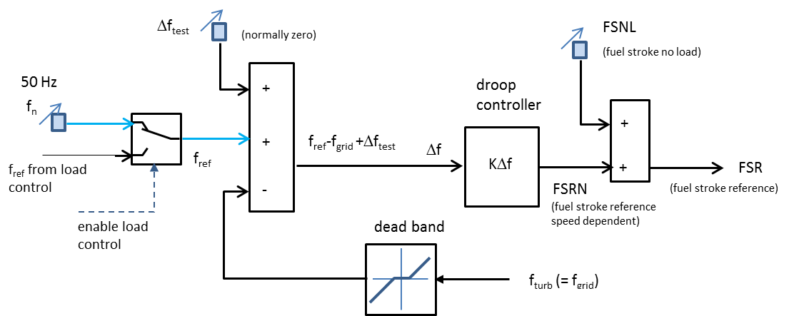
To manage the security of the electricity transmission and distribution grid in real time and co-ordinate the supply and demand for electricity in a manner that avoids too large fluctuations in frequency or interruptions in supply, the (T)SO – (Transmission) System Operator – prescribes in a (Transmission or Grid) Code – amongst other things – the outlines of the required reaction of generating units (GUs) connected to the grid on deviations in grid frequency. Especially with the introduction of an increasing capacity of intermittent renewable energy sources (i.e. wind and solar) there is an increasing need for an adequate mechanism to maintain the power balance during load disturbances in the grid. Prior to commercial operation new power plants shall demonstrate that they are able to provide the required primary response on a frequency deviation. Normally this is tested by inserting an artificial step change in frequency in the droop controller of the plant. The plant shall react by increasing the net power output with a certain percentage in a certain time frame.

Response of power output on a change in frequency of -200 mHz (red signal)
CerTa Veritas has a special fast data acquisition system (hardware and software) that can measure the frequency response and trigger signals with a high sampling rate. Besides net power output normally also gross power output, frequency and various control signals are measured. From the measured responses the so-called droop (= ratio of (negative) relative change in frequency and relative change in power output) is calculated and the time span to reach a certain percentage of the required resulting change in net power output.
Contact: